2.1 m Australian-Style Temporary Fence Kits
A 2.1 m Australian-style temporary fence order covers the panel, the matching feet, the clamps and the stays required by the site. Relia lists a 2100 × 2400 mm panel candidate. Send the screened and open runs separately so the quote can show the assembled height, support interfaces and fittings per run.
- Catalogue starting point
- 2100 × 2400 mm panel, subject to the selected option
- Site input
- Identify screened spans, returns, gates and ground conditions on the same plan
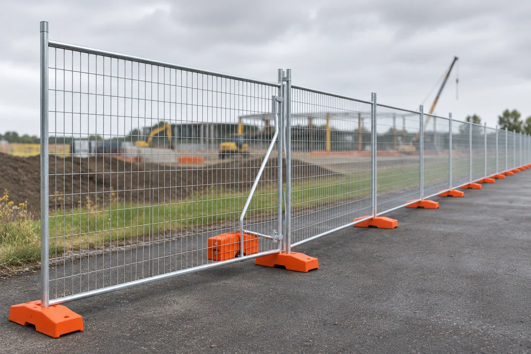
Open runs and screened runs have different inputs
Relia's 2.1 m construction panel lists 60 × 150 mm mesh and 3.5 or 4.0 mm wire options. Tell us whether your run is open or screened. We can identify the frame and base options for review with the installer.
Compare the 2.1 m panel and tube optionsMark the screened bays on your layout so the feet, braces and assembly information can be reviewed for those locations. Give screened and open runs separate quantities so the support review can follow the installed layout.
- Open runRecord the layout, panel width and ground condition.
- Screened runGive the proposed screen area and the project's approved wind conditions.
- Open temporary run
- Start with the 2100 × 2400 mm panel and check tube, foot and clamp on the same bay.
- Run with screening
- Mark the covered bays and use the approved wind and support conditions on the kit review.
- Before releasing the kit
- Record the chosen tube outside diameter and measured seating depth on a fitted sample.
The foot, leg and clamp on one drawing
Show the upper and lower interfaces in an assembled view. The sketch makes it easier to spot a leg or clamp that fits the panel on paper but sits differently at the actual site.
Review the assembled dimensions- Lower socketRecord the opening, insertion depth and orientation of the feet.
- Frame legProvide the outside tube dimension and the distance between the legs from the same datum.
- Top clampIdentify the tube sizes at the connection and the intended bolt position.
- Screened returnGive the reviewer the screen coverage, ground surface and location of each return or stay.
The foot and the frame share one interface
The post tube and base opening determine the fit. Give us the outside tube diameter and a base photo if you already have feet on site. An assembly drawing can confirm the insertion depth and the height above the pavement. Add a straight-on socket photo beside a scale if you plan to mix replacement parts with existing feet.
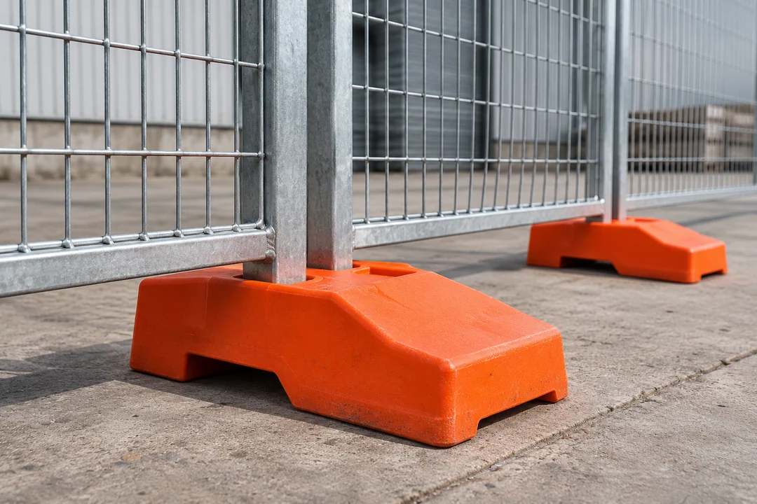
The assembled dimensions to put on the quote
The panel width is a useful stock reference. Centrelines, end returns and the base arrangement determine the installed run and finished height. Keep the dimensions that control the assembly on the same drawing. Write the frame dimensions and the assembled run dimensions in separate columns on the order sheet.
A quote entry the site crew can check. The 2100 × 2400 mm construction panel is listed with a 3.5 mm wire option. Record the chosen wire on the panel line. Give assembled height, the fitted foot and the clamp their own fields so a measured bay can be checked against the same offer.
| Dimension or condition | Catalogue reference | Acceptance input |
|---|---|---|
| Panel and aperture | 2100 × 2400 mm with a 60 × 150 mm opening | Finished top line, width datum and selected 3.5 or 4.0 mm wire |
| Frame and insertion | 32, 38, 42 or 48 mm outside tube options, with 1.5 or 2.0 mm walls and a 100 mm insertion note | Actual tube and foot fit, tube length and allowed clearance |
| Foot and surface | HDPE base field lists 600 × 230 × 150 mm and 15–20 kg | Selected base, allowed fixing, corner detail and handling weight |
| Screened bay | Screen, fence, support and ground together | Provide approved conditions and assembly-specific stability evidence |
Screening belongs on the site layout
A screen changes the conditions the assembled fence needs to satisfy. Put open and screened bays on the layout with corner and end positions. We can identify the product configuration to take through your site's approval process. Identify exposed corners and screened spans on the drawing used for the site wind review.
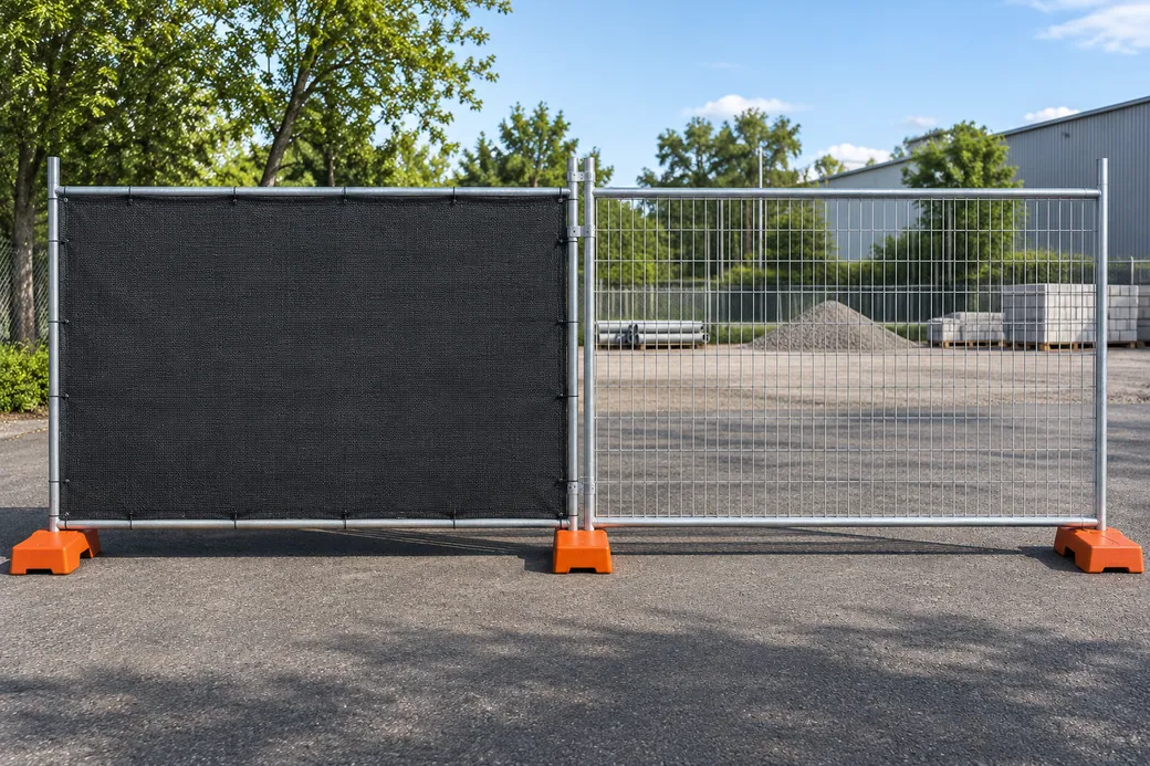
Stage the order around installation
Plan the order in the same units your crew uses to build the perimeter. Ask for installation sequence marks if the support parts will be unloaded at different entrances.
- RunsBreak the continuous line into measured segments.
- AccessList gate openings, corners and transitions.
- UnloadingSeparate panel packs and small components by phase.
A kit quote includes the loose parts
Check the proposed packing list against the assembly. Count feet, clamps and braces separately so you can identify shortages early and request spares for the items that move between sites. Count spare feet and clamps against the bundles that the crew can actually open in each phase.
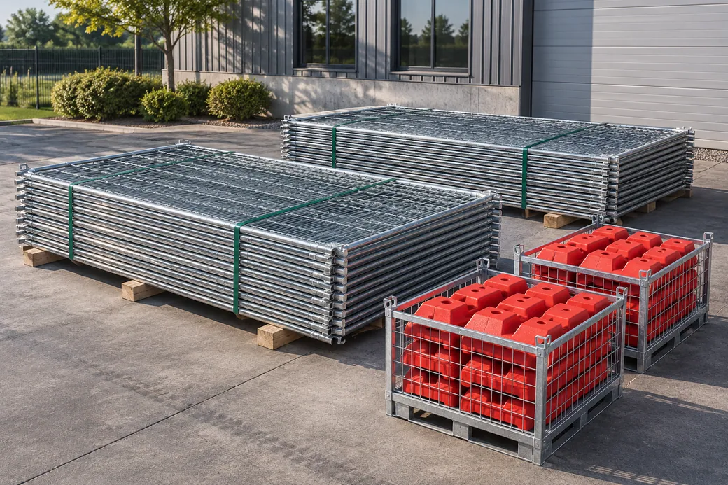
Frame fabrication and kit fit
The support legs, socket and top clamp form a chain of dimensions. A change to one part can affect the standing height or make a clamp sit at a different angle. Request the same fit check on the first assembly and on the shipped selections for the parts that mate.
- Panel and socket dimensions
- 60 × 150 mm mesh
- Selected frame tube
- 100 mm insertion reference
- Complete kit fit
- Material and dimensionsSize the steel parts together
The 2100 × 2400 mm reference panel lists 60 × 150 mm mesh. Identify the selected frame tube and base opening alongside the selected wire.
- Fabrication and fitFit the finished tube into the socket
The product record gives 100 mm as its insertion reference. A fitted sample also shows seating depth, joined width and clamp position.
- Inspection evidenceReview the kit in its actual setting
Record the feet, braces and clamps used on the sample. Where screening is planned, have the complete assembly reviewed for the ground and wind conditions.
Detailed checks for this order
- Set frame and mesh dimensionsFor welded infill, wire is arranged to the agreed grid and joined at intersections. Record the 60 × 150 mm opening and selected wire, then confirm the frame outside diameter, wall and dimensions on the same drawing.
- Check the frame in the baseMatch the chosen tube to the foot opening. The listing gives a 100 mm insertion reference. Record usable depth and the installed top height on a complete sample.
- Verify the support scheduleItemize each foot, clamp and brace. Confirm finish by part. For a screened bay, submit the full arrangement, ground conditions and wind requirements for project approval.
- Document the trial bayRequest an assembly drawing and the specification for the chosen components. Attach any supporting project-specific stability evidence required for the exact configuration.
TWI guidance on resistance welding · WorkSafe Victoria guidance on construction fencing
Panel options and the wind review
One item has a PVC finish in its title and a galvanized term in another field. Confirm the actual finish for every chosen part. WorkSafe Victoria flags extra wind support as a consideration when signs or shade cloth are attached. Use the full screened assembly and project conditions in that review. Record the finish choice for the legs, panels and fittings separately when you select a listing.
2.1 m galvanized construction panel
- Listed data
- 2.4 m reference width, 60 × 150 mm mesh and 3.5 or 4.0 mm wire options
- Confirm before purchase
- Drawn assembly, foot count, clamps, braces and final installed height
- Listed data
- 2100 × 2400 mm panel and multiple frame finishes shown
- Confirm before purchase
- Written finish and the scope of any supplied screen, support and fixings
Standards Australia AS 4687.2 scope · WorkSafe Victoria construction site guidance
Browse related products · Temporary Fence Panels
Related fencing orders on a live site
Use the renovation guide for movable diamond-mesh panels. Use the phased project guide when the temporary run will later be replaced by a permanent fence. Pick the adjacent guide for a different frame format before comparing feet or clamps.
Share the run layout and screen details
Send the panel run lengths, screen locations and assembled height. Include socket and clamp measurements when you will reuse any parts.
- Layout
- Segments, corners and openings
- Surface
- Pavement and fixing requirements
- Screen
- Area and approval documents
Shuyuan Road, Qingdao, Shandong, China
- [email protected]
- +1 404 203 0971
- Phone
- +86 18561762631