Galvanized Steel Grating for Walkways and Custom Platforms
For walkway grating, choose a candidate from the bearing-bar size, clear span and support layout on the approved platform drawing. Relia lists bearing-bar pitches of 30, 40, 60 and 100 mm across several entries. Use the exact bar size, cutouts and support conditions when requesting load and deflection evidence for a particular panel.
- First drawing mark
- Draw the bearing direction between the supports
- Check for release
- Tie span, bar geometry and load evidence to the identified panel
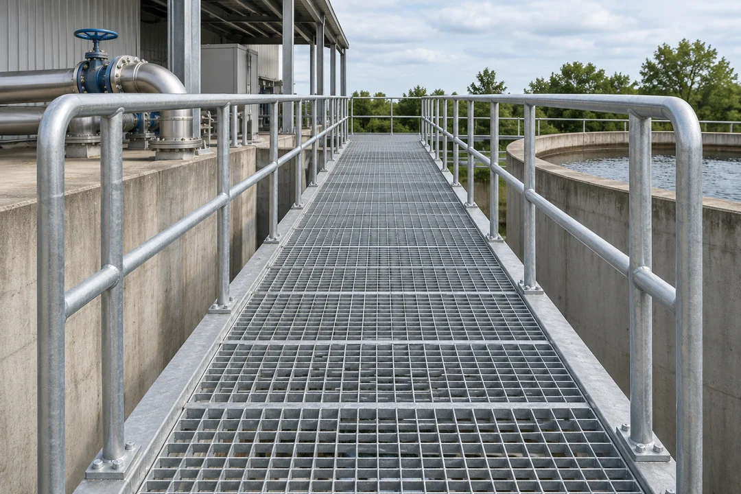
Bearing bar direction starts the comparison
Relia lists steel bar grating with several pitch choices and custom-size examples. We can read your panel drawing against those entries, then discuss bearing-bar geometry, cutout location and the information needed to assess the exact panel. Put an arrow on the bearing direction before comparing pitches in a product listing.
See the listed steel bar grating pitch choicesThe supporting span follows the bearing bars. Mark that direction on your drawing along with the actual supports and clear distance. Quote the bars and the load evidence against that specific arrangement.
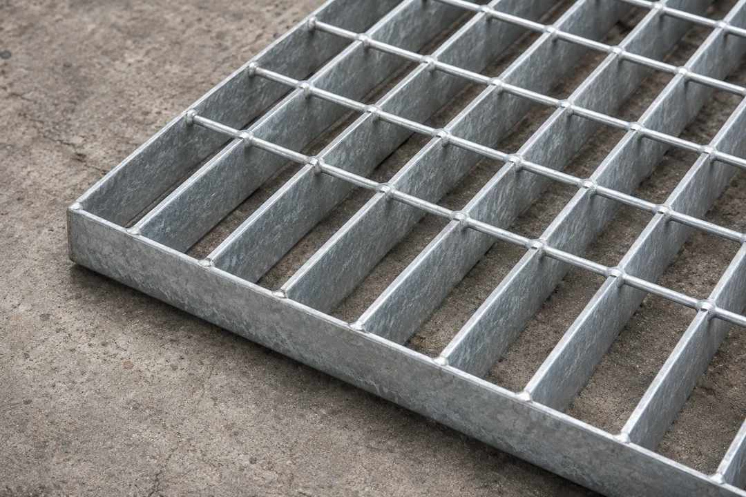
- Pedestrian platform
- Mark bearing direction, support seats, clear span and specified loading in one view.
- Cutout for an obstruction
- Show the opening, banding and the surrounding support on the approved panel drawing.
- Before ordering cut pieces
- Confirm the selected pitch, bar size and joining type for that drawing revision.
A panel drawing that shows where the load travels
Put the view of the grating, supports and cutout on one page. The same drawing can identify which dimensions belong to the grid and which dimensions define the unsupported span.
Read the bar and span dimensions separately- Support AMark the first seating surface and the edge on which the bearing bars land.
- Clear spanDimension the free distance between seats alongside the bearing-bar direction and depth.
- Cutout and edgeIdentify interrupted bars, openings and the edge detail to review on the approved drawing.
- Support BRecord the second seat and use the agreed span and applied loading for the applicable evidence.
Separate bar size, pitch and clear span on the drawing
The catalogue's 10 mm option is a cross-bar size. Pitch appears in separate fields. Label the direction of the bearing bars on each ordered piece including custom cutouts around equipment. Make the cross-bar diameter and both spacing fields explicit in the callout for the selected piece.
| Drawing input | Standard walkway | Made-to-drawing platform |
|---|---|---|
| Bearing bars | Bar depth and thickness, spacing and orientation | The same fields wherever cutouts affect supported bars |
| Cross bars | Size and spacing written separately | Grid alignment at openings and edge details |
| Supports and load | Clear span, seat geometry and approved load with its units | Same data plus support interruptions, clips and banding |
| Receiving | Item match, bearing direction and actual spans | Part-shaped drawing, revision, edge band and clip pack |
Cutouts and supports belong on the same view
Draw the openings around equipment and show where the bearing bars stop or continue. Include the proposed edge treatment and fixing positions. This lets us identify the custom pieces and the review information each needs. Show the cutout together with the adjacent supports in the view the approval team receives.
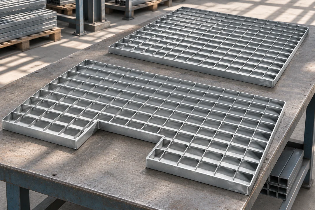
From drawing to checked parts
A drawing trail helps your installer identify the right panel at each location. Keep the drawing revision with each panel ID through fabrication and receiving.
- MarkAssign a part reference and bearing direction.
- ReviewConfirm cutouts, covers, supports, banding and clips.
- ReceiveMatch marked pieces to the latest accepted schedule.
A listing pitch needs its dimension label
Our catalogue examples include a 100 mm pitch and a 10 mm cross-bar option in the titles. Confirm which dimension each value describes and compare that exact model's geometry with the approved loading conditions. Check the pitch field and the 10 mm cross-bar option as separate dimensions.
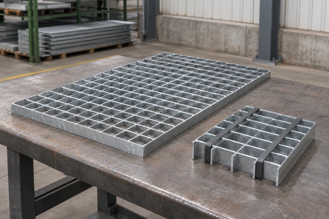
Review the safety documentation by model
Use a current grating item sheet and the applicable test or calculation evidence. Keep measured geometry separate from claims about the completed platform. Ask the project reviewer to tie the applied load and deflection criteria to the approved span and support.
Identify the panel configuration on the evidence sheet. The industrial grating listing includes a 100 mm bearing-pitch option and a 10 mm cross-bar option. Mark those as distinct fields if selected. Request the loading or deflection record for the chosen bearing-bar depth, approved clear span and support condition, with the panel drawing number attached.
- DrawingSpan, bars and supporting geometry
- RecordModel, load, direction and conditions
- ApprovalProject review of record and use
Grating fabrication around the bearing bars
Bearing bars span between supports. Cross bars keep the grid spaced, and cutouts can interrupt the bearing direction. Put all three on the approved drawing before the order is fabricated. Use the released drawing to check grating geometry, cutout location and bearing orientation before packing.
Measure between the supporting faces. Mark the bearing direction and any cutout on the drawing.
- Material and dimensionsDraw the bearing seats and clear span
Show the supporting faces and mark the bearing-bar direction. The selected pitch and the clear span describe different dimensions.
- Fabrication and fitDetail the grid and any interrupted bars
State the bar depth and thickness, grating type and cutout position. Review the edge and surrounding support before fabrication.
- Inspection evidenceMatch the finished panel to its approved loading
Use one dimension record for the actual supports, cutouts and fixing points. Request load information for that bar and support configuration.
Detailed checks for this order
- Distinguish bars, pitch and spanSpecify bearing-bar depth and thickness, its centre spacing, and the cross-bar data. Draw the actual clear span and the direction of bearing bars across it.
- Confirm joining and edge detailsState the grating type, such as welded or pressure-locked, if specified. Mark cutouts and their edge details. Have the surrounding support and bearing arrangement approved when a cutout interrupts a bar.
- Inspect the finished panels before dispatchCheck panel dimensions, cutout positions, bearing direction and fastening details after finishing. Request data tied to the actual grating type, support and specified loading.
NAAMM Metal Bar Grating Manual · OSHA walking-working surface requirements
Published grating geometry and the load evidence to request
Use the catalogue to choose candidate geometry. A project load or deflection check needs the exact material, clear span, support, bar dimensions and load case. NAAMM publishes separate standard and heavy-duty manuals. US workplace walking surfaces are subject to the applicable OSHA maximum intended load requirement. Quote the chosen bar option and applicable documentation together for each required panel.
- Listed geometry
- Bearing pitch 30/40/60/100 mm, cross-bar size 6/8/10 mm and cross-bar pitch 24–200 mm listed
- Confirm before order
- Depth and thickness behind the listed bar code, finish and model-specific load/deflection record
- Listed geometry
- Same nominal pitch choices with customized length and 6/8/10 mm cross-bar sizes
- Confirm before order
- Cut shape, finished dimensions and the drawing with support, seats and clips
NAAMM bar grating manuals and design data · OSHA walking-working surface requirements
Browse related products · Steel Grating
Other drain and sheet-metal decisions
A vehicle-crossed drain has a different load input. Cabinet ventilation screens use opening and edge details for a separate task. Move to the trench guide when the scope includes vehicle crossing load or a retained drain seat.
- If vehicles also cross the gratingSteel Trench Drain Grating for Vehicle Traffic at Loading YardsStart a separate review for the wheel load and actual support conditions.
- If the grating sits in a retained frameReplacement Steel Trench Grating for Car-Wash DrainsMeasure the ledges, recess and flush level across the opening.
Send the approved platform and loading information
Send the identified platform drawings, clear spans, support and opening details, and approved loading information for each panel.
- Drawing
- Panel outline, cutouts and supports
- Loading
- Approved conditions with units
- Fit
- Clips, banding and part IDs
Shuyuan Road, Qingdao, Shandong, China
- [email protected]
- +1 404 203 0971
- Phone
- +86 18561762631