Galvanized Palisade Bays for Industrial Fence Extensions
Start a palisade extension with a survey of one retained bay. Record pale profile, rail height, post spacing and how the first new bay joins the fence. Relia’s galvanized and powder-finish examples can help shortlist an option once the drawing shows the profile and the parts that will stay.
- First site task
- Survey a sound retained bay and photograph the pale profile
- Release evidence
- One fitted tie-in with a recorded rail alignment and chosen finish
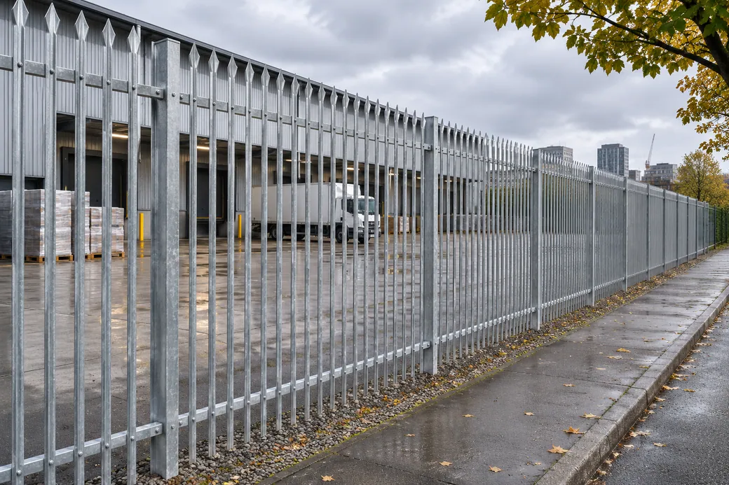
The narrow profile determines the visual match
Relia lists galvanized and powder-coated palisade fence candidates. Send us an end photo, a pale cross-section and rail holes measured from one datum. We can review suitable catalogue options and identify which components still need a transition drawing. Pick a sound visible pale and record its shape and finish as the reference.
Review a galvanized and powder-coated palisade candidatePhotograph the pale face and side together. Measure the section and rail fixing pattern. A 6 ft catalogue height helps shortlist candidates, while the actual profile and connection fix the extension detail.
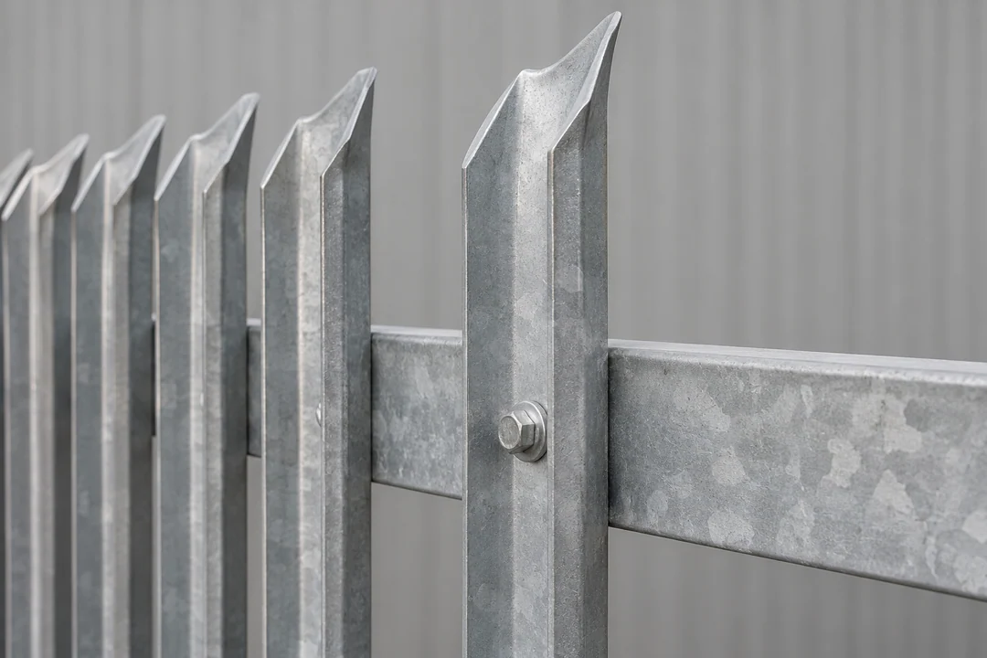
- Matching the existing elevation
- Record the pale profile, centres and visible top detail on the retained bay.
- Joining old and new rails
- Use the same datum for hole centres and the end offset at the transition.
- Before repeating the bay
- Approve one finished pale, rail and fastener fit.
The retained end beside the new bay
Draw the old end first, then carry its rail and fixing heights into the proposed bay. The paired views give the installer a clear location for the first joint.
Prepare the separate tie-in view- Retained bayMeasure the pale profile, rail heights and spacing from a visible datum.
- Tie-in jointShow the rail end, fasteners and where the existing post or foundation remains.
- First new assemblyReview the assembled section for alignment and finish before confirming all repeats.
A palisade tie-in measured at the retained end
Use an end-on pale photo and the same datum on the old and proposed rail. State whether spacing means centres or clear gap. Show post centres, rail elevations and the joint fastener positions on a common drawing.
| Interface | Measure on the existing fence | Verify for the extension |
|---|---|---|
| Pale section | Profile, actual outer measurement, material thickness and spacing | Replacement profile and visible line match |
| Rail interface | Rail section and centre-to-centre hole position | Pattern, enough overlap and matching fasteners as drawn |
| End post | Outside section, old centre and offset to the adjacent bay | Connection position and finish on the actual post drawing |
The tie-in needs its own view
A face drawing sets overall dimensions. Add a side view of the last post and rail end so we can see how the new section would meet them. Mark the change if the old bay is uneven or out of square. Give the fabricator the retained end profile and the space available for the connector.
Record the first joint beside the old rail. Use the industrial palisade range to shortlist the proposed finish and height. Give the fabricator a front and side view of the old rail end, plus the fastener spacing from the same datum. Request a drawing with the retained end and new bay identified separately.
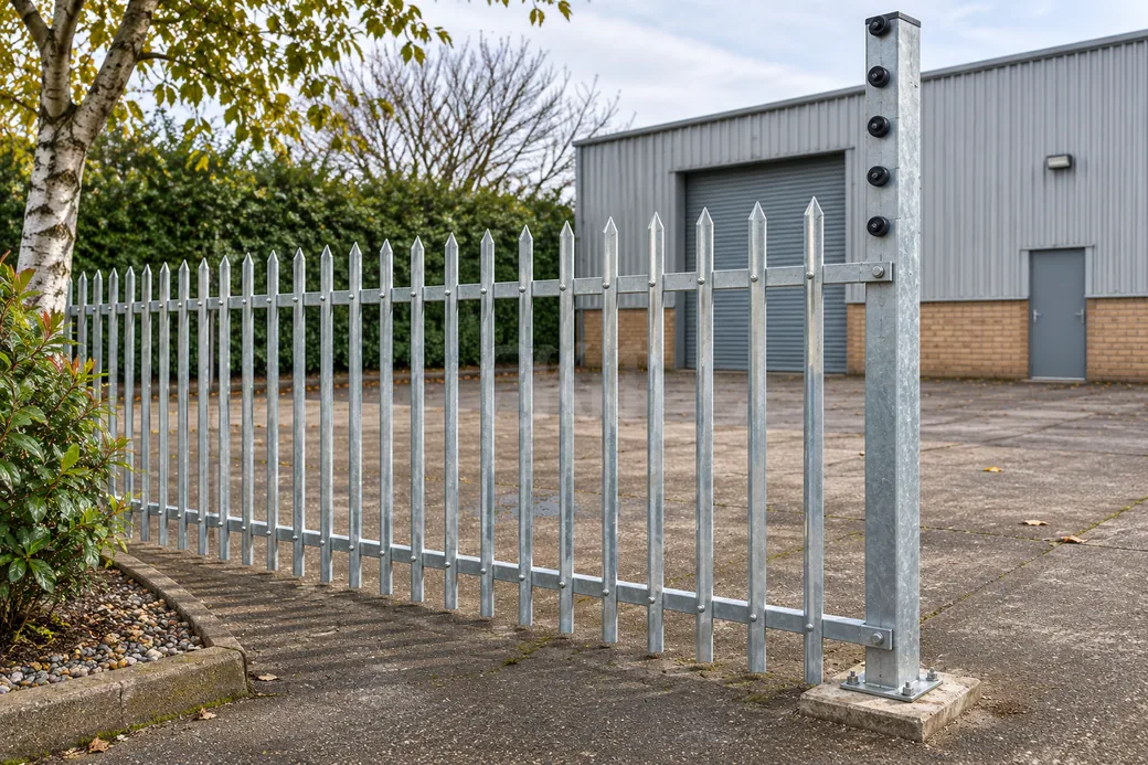
Approve one matching section before the order
Choose a representative interface. Keeping that specific check with the order helps the installer and purchase team. Set a trial at the extension point while existing clearances can still be measured.
- MeasureKeep the datum on the old end.
- CompareUse the candidate section and rail drawing.
- ApproveRecord the agreed joint and selected coating.
Finish and spares go on separate order lines
Both catalogue candidates list galvanized and powder-coated finishes. Check the colour from a sample when the extension is visible. Include spare pale, rail or fastener parts as separate lines if your maintenance team needs them. Include spare corresponding fittings and visible finish requirements on distinct quote lines.
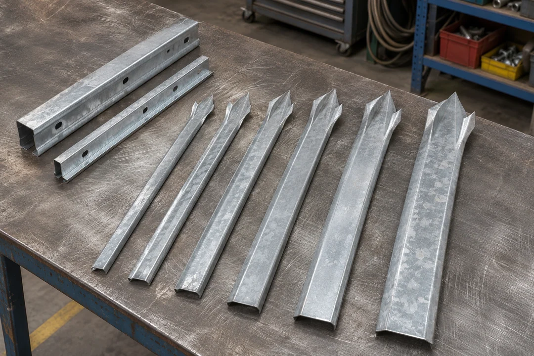
Pale forming and rail fit
A palisade bay depends on the selected pale section and the way it attaches to existing rails. Consider the profile, punched holes and finish together when checking the fit. Review the fixed rail against the chosen pale before releasing the finish or drilling schedule.
- Material and dimensionsRecord the formed pale shape
Start from a usable retained section. Note pale thickness, width and the top detail against an elevation.
- Fabrication and fitCompare rail holes from the same datum
Mark their centres and end distance on both sections. Agree the zinc and powder sequence for the quoted parts before fitting.
- Inspection evidenceReview one finished transition bay
Use the actual pale, rail and fastener in the trial. The result establishes the visible gap and the fitting reference for further bays.
Detailed checks for this order
- Define the pale cross-section and elevationPut the formed shape, width, thickness and top detail in the drawing. Include the spacing and the measuring points used on the retained bay.
- Check rail preparation against the existing endReference the hole centres and end offset from one datum. Compare a new pale, rail and fastener sample to the adjoining structure before confirming the remaining quantity.
- Inspect the finished tie-inConfirm the zinc and any powder-coat sequence by item. Check hole and fastener fit after coating and document the sample elevation so the finished extension can be compared to it.
Palisade product data and the drawing check
The shared specification lists vertical member spacing options of 100, 110 and 120 mm and a 1.2–3.0 mm thickness field. Another post option is ambiguously entered in the catalogue. Use the supplier drawing for exact post dimensions and determine whether each range applies to the pale, rail or post. Resolve profile, colour and mounting choices with a matching drawing before comparing listed items.
- Listed configuration
- 7 × 6 ft nominal, 1800/2000/2400 mm width options, galvanized and powder-coated finish listed
- Confirm before order
- Real clear width, pale and rail section, colour sample
- Listed configuration
- 1800/2100/3000 mm height options among other nominal fields, galvanized or galvanized and powder coated terms
- Confirm before order
- Agreed top line, post centre, joint and component coating
American Galvanizers Association duplex system guidance
Browse related products · Steel Palisade Fencing
Related fence profiles and post work
If the frontage uses picket fencing, quote that line from its own geometry. Use the post guide for the slab or ground interface of a new run. Check the post work guide if the extension uses a new footing or a retained mount.
Send photos of the end bay and a section drawing
Send photos and dimensions of the last sound bay, the tie-in joint, intended finish and extension length. Mark any gates or change in level.
- Old fence
- Pale, rail and terminal details
- New run
- Length, finish and positions
- Fit
- Required sample or connection drawing
Shuyuan Road, Qingdao, Shandong, China
- [email protected]
- +1 404 203 0971
- Phone
- +86 18561762631