Perimeter Fencing for Ground-Mounted Solar Farms
For a ground-mounted solar farm, turn the perimeter drawing into run sections with ground changes, access widths and spare parts identified. Relia lists rigid perimeter panel and support examples. Set the installed mesh and mounting basis by section, and put vehicle openings and maintenance gates on their own schedule lines.
- Site schedule
- Run IDs, grade changes and vehicle openings on one drawing
- Receiving plan
- Pack references match each installation segment and spare line
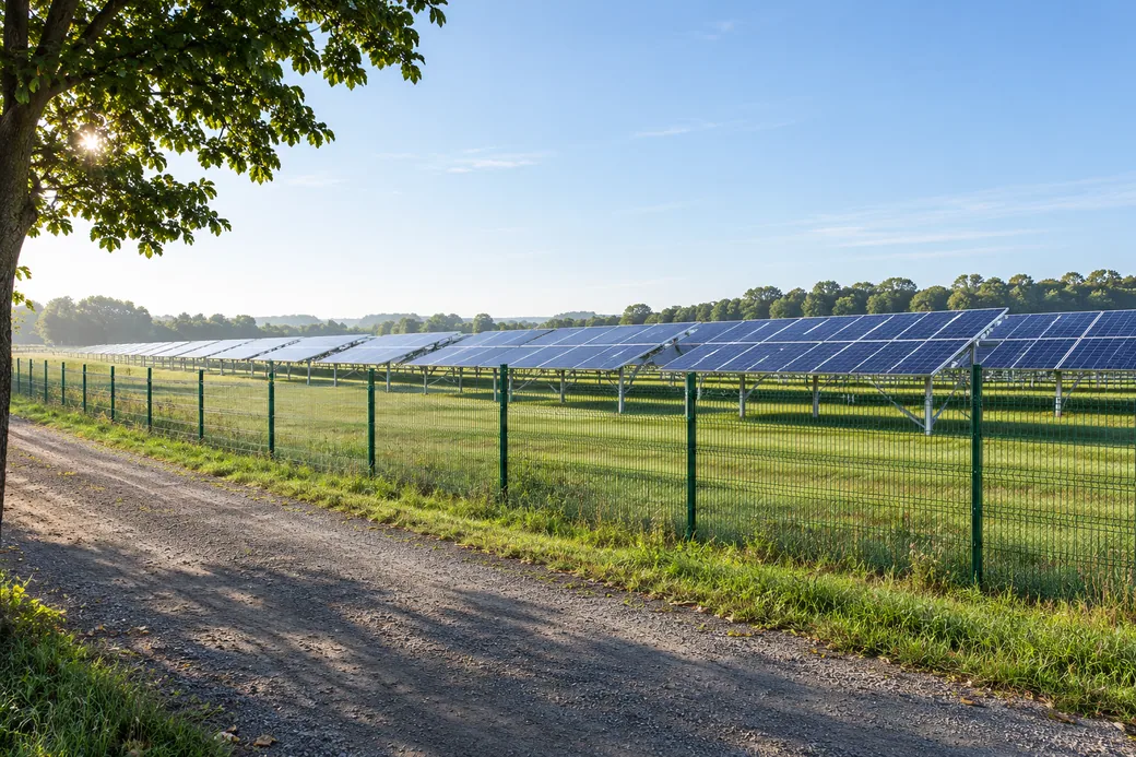
Rigid panels give the long run a repeatable unit
Relia lists V-bend welded panels, chain-link rolls and separate post options. Send the perimeter and gate schedule. We can review the relevant catalogue options by segment and identify the corresponding posts and fittings to price. Give the standard panel and its selected mounting a common schedule code.
Review a V-bend fence panel for repeatable baysOur 3D catalogue example lists 50 × 100 mm mesh and round or square post choices. Use the real run lengths and changes in level to verify how a panel-based system would fit your plan.
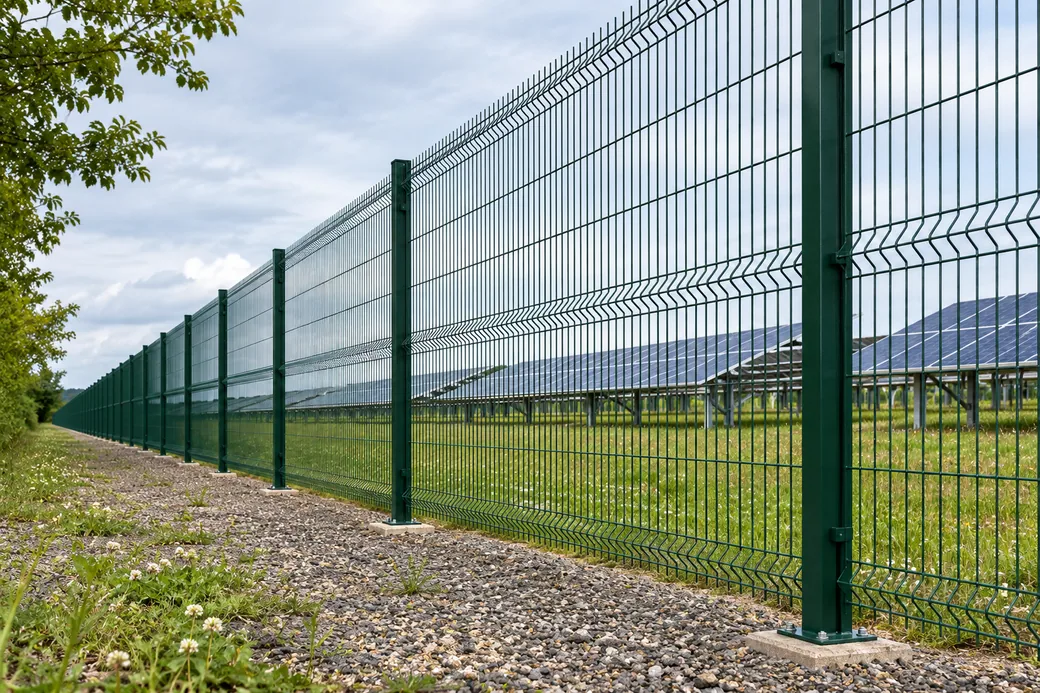
- Repeated rigid bays
- Put each panel width, bracket offset and post centre against the approved segment.
- Woven long run
- Schedule roll lengths and terminals around corners, gates and grade breaks.
- For maintenance access
- Review gate openings with the site team and identify spares by the segment that uses them.
Divide the solar perimeter into workable zones
Use one top-down drawing for the owner, the quote and the receiving team. Show the lines that repeat and the places where vehicles, grade changes or servicing require a separate specification.
Review the full site schedule- Long repeat runName the selected mesh, height and support conditions for the standard installed span.
- Grade changeMark the slope, step or substrate that triggers a different post or profile.
- Vehicle and service accessRecord the clear width and separate hardware for routes used by people and equipment.
- Spare and receipt zoneLabel inventory so future maintenance can identify the fitted mesh, posts and connections.
The site schedule for vehicles, slopes and spares
Keep the maintenance route and gate width on the same diagram as fence ends. Use that drawing to give each section a distinct parts and delivery line. Record each run, access point and maintenance stock line separately in the takeoff.
Keep the post decision tied to its segment. A rigid V-bend panel and an 8 ft chain-link candidate require different connections. Give each section its access width, grade change and support detail. Put the matching spare panels or fittings on identified lines so a maintenance order can use the same site schedule.
| Zone | What to compare | Evidence or acceptance input |
|---|---|---|
| Long straight run | Bay count or roll cut list with endpoints marked | Widths or roll lengths, supports and spares |
| Vehicle entrance | Clear opening and approach used by maintenance vehicles | Project gate detail and fence terminal parts |
| Change in level | Field level and panels or fabric applicable to the layout | Mounting section, resolved corners and end conditions |
| Support choice | Each post profile, wall and matching fitting as separate fields | The actual proposed assembly and approved ground condition |
Maintenance vehicles shape the openings
Show the clear openings and approach routes your approved plan requires. The fence quote should identify boundary sections, support conditions and any gateway interface you want included for each opening. Show the direction and approach of the maintenance vehicle on the gate view.
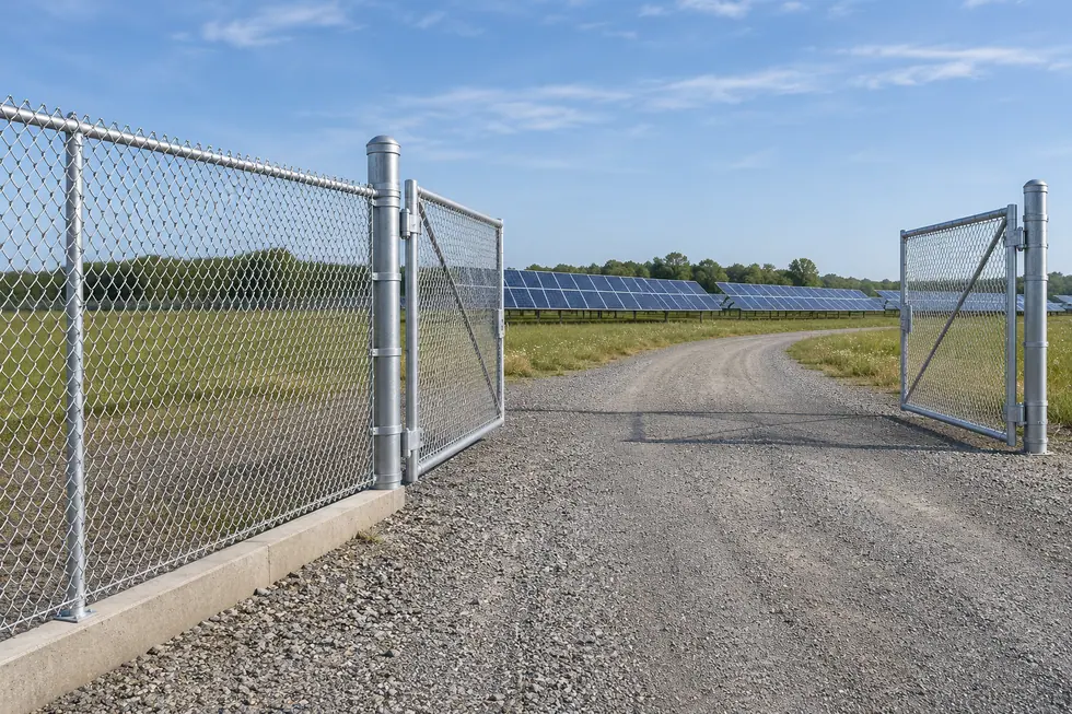
Separate post options by ground condition
Inventory the site by the project layout so each length has a suitable support decision to review. Keep support and mounting details linked to the actual ground condition label.
- ZoneRecord terrain, surface and length.
- SupportConfirm proposed post section and mounting.
- FittingList clamps or tension parts and end conditions.
Organize receiving by segment
A long site can have several installation areas. Label each pack by the intended run and keep the loose fittings with the right group. Use the quote to confirm those details before the installation team receives stock. Assign pack and bundle marks by segment in the sequence the installers will receive them.
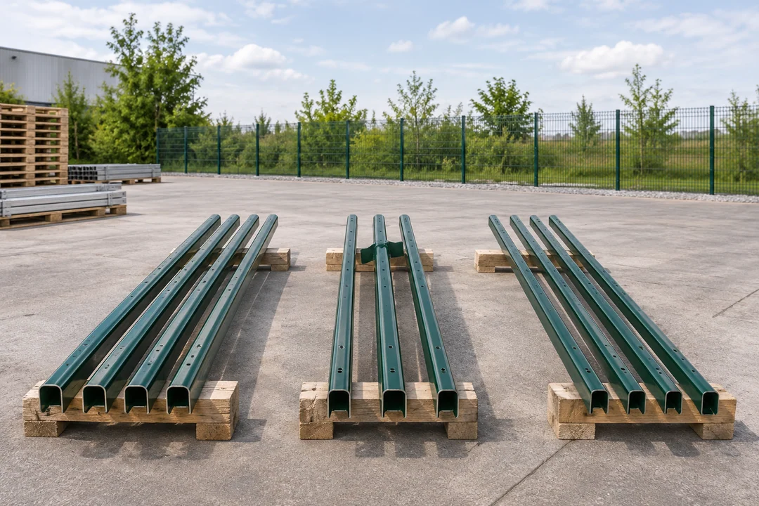
Manufacturing and delivery by perimeter segment
A rigid run is ordered in individual panels. A chain-link run is ordered in lengths of fabric with terminal assemblies. Let the site drawing define where the factory piece counts and roll cuts begin and end. Review drawings and part data before the segment packs are released for delivery.
- Material and dimensionsMark each gate, grade change and ground section
The permanent line may use rigid bays or woven runs. Define the gates and vehicle maintenance access on the selected layout.
- Fabrication and fitWrite a parts schedule for each system
A rigid panel needs the rib, width and bracket offsets. Woven fabric needs terminals, roll lengths and a separate fitting list.
- Inspection evidenceCheck a difficult transition before dispatch
Fit a representative gate or grade-change detail. Mark bundled parts and spares by the segment where they will be used.
Detailed checks for this order
- Make the rigid bay repeatableSpecify grid, rib and panel width with the selected bracket offset and post centres. Use the approved detail at changes in grade.
- Order woven fabric at the correct run breaksConfirm diamond, height, coating, edge treatment and roll length. Give end, corner and gate fittings separate lines against the runs they serve.
- Check the built sample and the receiving listVerify fit at a representative gate approach or grade change. Mark packs by segment or gate and list extra fittings against the panel or roll type.
TWI guidance on resistance welding · CLFMI chain-link fabric product manual
Perimeter models and maintenance scope
Use the optical and access function in your solar site brief to select the fence assembly. The PV operations guidance supports keeping access and site maintenance needs in project planning. For the chain-link and separate U post, reconcile finish fields before ordering. Select model candidates with the boundary height, terrain and access requirements visible.
- Published data
- 50 × 100 mm, 3.0 mm example and three standard width choices on the catalogue record
- Confirm with the zone schedule
- Net bay, support layout and installation drawing
- Published data
- 8 ft nominal and 10–50 m roll lengths by option
- Confirm with the zone schedule
- Coating sequence, end and tension fittings and actual length
- Published data
- U section, 25.4–119.4 mm width range, optional anchor-plate field
- Confirm with the zone schedule
- Actual U section, finish and fit to the proposed system
NREL photovoltaic operations and maintenance guide · ASTM F567 chain-link installation practice
Browse related products · 3D Curved Welded Mesh · Chain-Link Fencing · Fence Posts
Choose the system and the mount together
The warehouse comparison has a useful side-by-side selection method. The post guide helps with supports at hard surfaces, and the roof guide serves a different solar procurement need. Use the post-specific guide to complete the mount after selecting the perimeter system.
- Where foundations or paved areas varyBase-Plated and Embedded Posts for Permanent FencesSpecify the approved mount and height datum for each section.
- When weighing the two fence systems3D Welded Mesh and Chain-Link for Warehouse PerimetersCompare a rigid bay and woven run with an equivalent supply scope.
Send the boundary map and maintenance requirements
Send the boundary plan, run quantities, grade and surface details, gate clear widths and spares. Include your delivery and installation sequence.
- Site
- Boundary, slopes and access
- System
- Panels or rolls with matching mounts
- Delivery
- Quantities and segments by phase
Shuyuan Road, Qingdao, Shandong, China
- [email protected]
- +1 404 203 0971
- Phone
- +86 18561762631